
As an oil and gas industry pulsation control specialist, I’ve consulted with many contractors in numerous US shale plays about optimizing mud systems on older rigs to achieve maximum performance and profitability.

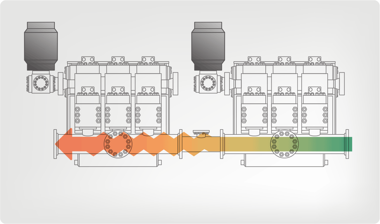
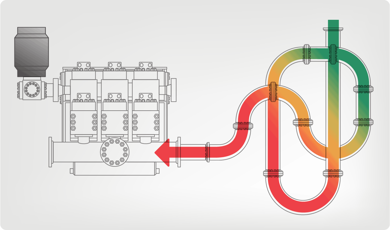
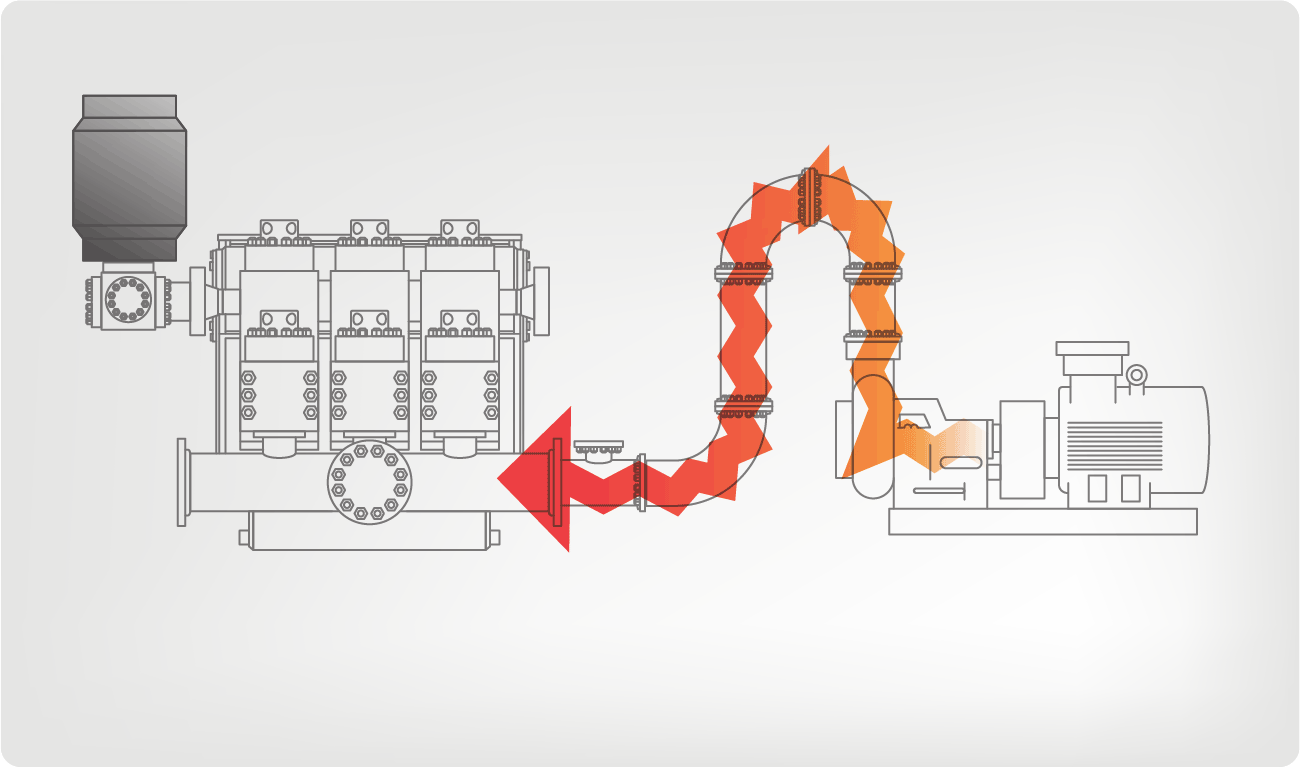
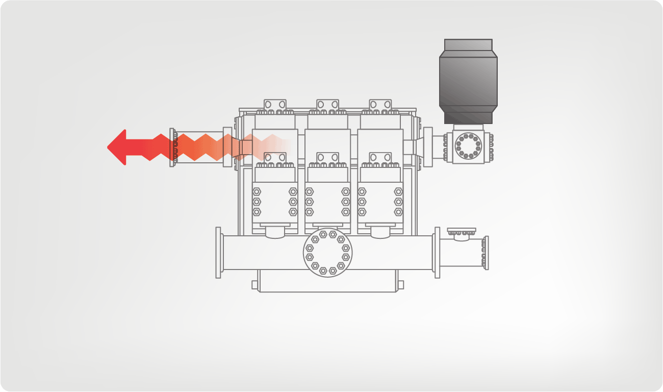
A common challenge in consults with contractors is, many older rigs built in the pre-fracking era have mud systems lacking appropriate piping size, pulsation control technology, and structural design. These are essential to handle the 7500 psi and up to 1400 BPM rates needed to achieve the aggressive drill plans of today and beyond.

The downside of operating dated mud systems can be significant decreases in performance, efficiency, and safety. Besides, aging systems require frequent maintenance and often encounter unexpected repairs that increase unplanned downtime. The net result is significant profit loss due to delayed drill plan completion and loss of potential prospective contracts due to drilling plan goals not being achieved.

The good news is older mud systems can be modified to meet the aggressive targets of today’s horizontal and directional drilling plan contracts.

Below are five common operational efficiency challenges I’ve encountered in working on contractor rig consults and suggested solutions to optimize a mud system’s performance, efficiency, and ultimately contractors’ long term profitability.

How to Optimize Your Mud Pump System for Next-Level Performance and Profitability

Download the free white paper now.

1. Single Supply Line

It’s common for older rig designs to see a single supply line installed for two mud pumps. With a single feed design, fluid deprivation often occurs at the second pump. The net result is “pump chatter,” a water hammer effect, and a supply choke for the secondary pump with high flow rate requirements.

“Pump chatter” occurs when reciprocating pumps have the opportunity to interact with other pumps. Often “pump chatter” from a reciprocating pump occurs without a proper suction stabilizer installed and is usually limited to a charge pump.

Solution:
Feed Each MP with an Individual Supply Line

Installing an individual supply line for each mud pump ensures pumps have adequate fluid to prevent cavitation.

Isolating pumps are crucial in piping design to limit the negative impacts of compounding signatures.

For example, I’ve seen a rig piping design where both reciprocating pumps were feed through a single supply line, exposing both pumps to each others’ mechanical and acoustic signatures as well as the charge pump. The design ultimately caused cavitation issues and premature pump expendable failure resulting in unplanned repairs and downtime.

2. Insufficient Supply Piping Size

Another common challenge I’ve seen is insufficient supply piping size resulting in mud pumps that physically can’t handle the GPMs without frequent cavitation.

For example, a 6″ steel pipe, with a maximum flow rate of 800 GPM at a velocity of 8.9 Ft per second, would not be capable of delivering the appropriate GPM flow rate without cavitation.

Solution:
Increase Supply Piping Diameter

Many pump manufacturers suggest or require a supply line piping design to be one to two sizes larger than the pump’s suction connection and use an eccentric type pipe reducer at the pump with the flat side up to avoid a possible vapor pocket. Again, supply lines should be for individual pumps.

Supply lines should also be as short and direct as possible with a minimum number of turns.

3. Extreme Supply Line Length & Encumbrance

Suppose the supply line is too long and has multiple encumbrances such as flow tees, elbows, 90-degree angles, and ball valves. In that case, a significant frictional loss will result in the potential to create substantial turbulence to the pumped media.

Solution:
Make Supply Line More Direct and Closer to the Mud Pump

As previously mentioned, the supply lines should be as close to the individual mud pump as possible. Making the lines more direct and more immediate to the mud pumps will minimize pumped media turbulence resulting in more efficient performance.

Supply lines should be as short and direct as possible with a minimum number of turns.

Depending on a rig’s original design, skid placement and piping systems’ extensive remodeling may be needed to achieve optimal efficiency.

4. Insufficient Suction Stabilization

I’ve run into several instances of insufficient suction stabilization on rigs where a “standpipe” is installed off the suction manifold. The thought behind this design was to create a gas-over-fluid column for the reciprocating pump and eliminate cavitation.

When the standpipe is installed on the suction manifold’s deadhead side, there’s little opportunity to get fluid into all the cylinders to prevent cavitation. Also, the reciprocating pump and charge pump are not isolated.

The gas over fluid internal systems has limitations too. The standpipe loses compression due to gas being consumed by the drilling fluid. In the absence of gas, the standpipe becomes virtually defunct because gravity (14.7 psi) is the only force driving the cylinders’ fluid. Also, gas is rarely replenished or charged in the standpipe.

Solution:
Install Proper Suction Stabilizers

Installing a suction stabilizer from the suction manifold port supports the manifold’s capacity to pull adequate fluid and eliminates the chance of manifold fluid deficiency, which ultimately prevents cavitation.

Another benefit of installing a suction stabilizer is eliminating the negative energies in fluids caused by the water hammer effect from valves quickly closing and opening.

The suction stabilizer’s compressible feature is designed to absorb the negative energies and promote smooth fluid flow. As a result, pump isolation is achieved between the charge pump and the reciprocating pump.

The isolation eliminates pump chatter, and because the reciprocating pump’s negative energies never reach the charge pump, the pump’s expendable life is extended.

Investing in suction stabilizers will ensure your pumps operate consistently and efficiently. They can also prevent most challenges related to pressure surges or pulsations in the most difficult piping environments.

Sigma Drilling Technologies’ Charge Free Suction Stabilizer is recommended for installation. If rigs have gas-charged cartridges installed in the suction stabilizers on the rig, another suggested upgrade is the Charge Free Conversion Kits.

5. Pulsation Dampeners Installed on Blind End of Manifold

In a situation where both pulsation dampeners are installed on the discharge manifold’s blind end, in general, energy along with the fluid will take the “path of least resistance,” which in this case would be down the production line, not to the manifold’s blind end.

Solution:
Install Pulsation Dampeners In-line with Flow

Installing the pulsation dampeners above the system’s fluid flow and in-line with the pumped media’s direction will significantly increase energy exposure and increase mitigating results. Regardless of the dampening system employed, getting more energy to the pulsation dampener is highly recommended.

Sigma Drilling Technologies recommends the Charge Free Pulsation Dampener utilizing the Charge Free Conversion Kits. When utilizing existing equipment, Sigma recommends converting existing gas-charged pulsation dampeners with the Charge Free Conversion Kits.

Summary

Chances are, if you’re a contractor running rigs with older mud systems, you may have encountered some or all of the challenges discussed.

We want to invite you to schedule a free consult to help determine areas of opportunity in upgrading your mud system.

We look forward to discussing how Sigma Drilling Technologies’ pulsation control equipment solutions can improve your drilling rigs’ efficiency, performance, and profitability.